FAQS
Alternate File Extensions
Q. After upgrading ALPHACAM to the current version, when outputting NC code, ALPHACAM doesn’t use the file extension recognized by the CNC machine. What is wrong?
A. Turn on the free Add-In called “Alternate File Extension”.
By default, when using the Output NC function within ALPHACAM, the file extension is “.anc”.
Example: outputNCtest.anc
Some CNC machines require this file extension to be something other than “.anc”. The post processor used during the creation of the program from the Output NC function can control the type of file extension.
To turn on the “Alternate File Extension” Add-In in ALPHACAM, click on the Utils menu and then click on Add-Ins.

Select the “Alternate File Extension” option below the Free Options section.

When using the Output NC function, saving, and naming the file, the file extension can also be changed to any available formats supported by the working post processor.

Shortcut keys for ALPHACAM
The following hot keys help during geometry creation:
- F1 – Help
- F2 – Auto Snap On/Off
- F3 – Ortho Mode On/Off
- F4 – Close and Finish
- F5 – Grid Snap On/Off
- F6 – Snap to End Point
- F7 – Snap to Mid Point
- F8 – Snap to Center
- F9 – Snap to Intersection
- F10 – Snap to Tangent
- F11 – Snap to Perpendicular
- F12 – Snap to Parallel
The following shortcut keys allow you to quickly bring up regularly used commands in ALPHACAM:
- Ctrl + N – New File
- Ctrl + O – Open File
- Ctrl + Insert – Insert ALPHACAM Drawing
- Ctrl + S – Save
- Ctrl + I – Input CAD
- Ctrl + L – List NC
- Ctrl + M – Clear Memory
- Ctrl + P – Printer/Plotter
- Ctrl + Z – Undo
- Ctrl + Delete – Delete
- Ctrl + F – Start Point
- Ctrl + H – Change
- Ctrl + A – Zoom All
- Ctrl + W – Zoom Window
- Ctrl + B – Zoom Previous
- Ctrl + R – Redraw
- Ctrl + G – Ghost Tools
- Ctrl + T – Text
- Ctrl + D – Dimension
- Ctrl + U – User Layers
- Ctrl + E – Edit Operations
Utilizing Free Add-Ins
Utilize Free Add-Ins in your ALPHACAM software. Free Add-Ins can be accessed from the UTILS pull down menu. After highlighting a particular Free Add-In, click the info button for a brief description and explanation for each. You’ll find that some of these Free Add-Ins can make your day to day programming easier, faster and more efficient.
Fixing Vista Permissions Issues
Are you having issues with getting Alpahcam to run correctly with a Microsoft™ VISTA™ operating system ? Here is the proper way to turn off the UAC (User Account Controls). Although this may not solve all issues, we have found this to alleviate lots of headaches.
– Go to your Start menu and choose Control Panel as shown:

– From the Control Panel, select the option to “Turn User Account Control on or off”

– Click on the tick box to turn off the User Account Control, then click “OK”

This should do the trick.
How to Update Your Standalone License File

Please note, this is for standalone licenses only. This tech tip is only applicable to licenses generated in the United States.
A. When you receive this message, it is a simple license update.
1) Select the OK button, and then your lock code window will appear.

2) Select the WEB button. This will bring you to the ALPHACAM Support page.

3) Login with credentials you set up previously. Once you are logged in,

4) Select the Request License button and select Request License again under My License.

5) When this is selected, another page will appear, and this will give you the option of updating your license if your SMP (Software Maintenance Plan) is up to date.

6) Select Click here, to update your license to the version you requested. You will then see the Upgrade License page.

7) Once you have reached this point, select List Licenses, which will bring you to your download page.

8) Please note the Software Version line. Select the Download button; select Save, then save it in a location that you will find easily e.g. your Desktop.

9) Select the Save button

10) Once the license file Acam.upl is saved, select the Browse button in the lock code window, select the Desktop button or where you saved the Acam.upl file, select the Acam.upl file, and select Open.
You should then see the following window stating the license file updated successfully.

Select the OK button and select Retry on the lock code window.
ALPHACAM will launch successfully.
How to Update Your Network License File
Q. I installed the most recent ALPHACAM release on my computer and I get a message stating “License not Available for this version”
What do I do?
![]()
Please note, this is for network licenses only. This tech tip is only applicable to licenses generated in the United States.
A. This message means it is a simple license update. To request your license update, please do the following:
1) Select the OK button and your current window will disappear.
2) Send an email to acam.support@planitsolutions.com and request your license to be updated.
On the Subject Line of your email please write “License Update Request – Company Name “ (to indicate your company name).
3) You will then receive an email from the ALPHACAM License Support Site advising that your license has been activated and is available for download as follows:

4) You will need to log in using your email address and your password. If you have forgotten your password, you can request a reminder from the support site home page by clicking on:
Password Reminder
5) Select the link http://support.ALPHACAM.com/ and continue with the login procedure.

6) Select List Licenses, which will bring you to your download page as shown below.
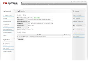

Important:
Please note the Software Version field.
7) Select the Download button.

8) Select the Save button.
9) Save the acam.upl file in a location that you will find easily (Ex: your Desktop).
10) Browse to the ALPHACAM installation DVD and locate the WlmAdmin.exe file located in the Sentinel_RMS_Licensing\Administer and Monitor folder.
11) Execute the WlmAdmin.exe utility by double clicking the file name and the WlmAdmin window will be displayed as follows:

12) Click the + in front of Subnet Servers (your license server will show up under the Subnet Servers).
13) Right mouse click and highlight/select your server name.
14) Highlight/select
Add Feature
From a File
To Server and its File
15) The following window will then be displayed, looking for the acam.upl file you downloaded and saved on step #10 (in our Ex: your Desktop).

16) Select the down arrow on the right hand side of the “Look in:” field, and scroll up to your Desktop or the location where you saved the acam.upl file.
17) Select the acam.upl file and then the following window will be displayed showing that the license has been read and successfully installed.
Important: Please note that this is not the total number of seats that you have purchased.

18) Select the OK button.
19) Select the Retry button on the Lock Code window.
20) You will now be able to launch ALPHACAM successfully!
How to Remove Unwanted Rectangle Lines in ALPHACAM
If you get multiple lines across the screen when trying to create a rectangle using ALPHACAM V8, try the following:
Please make sure your video card drivers are current and then follow these steps:
On a computer running the XP Operating System, you may have to slow your hardware acceleration down on your video card:1) Do a right mouse click on your Desktop
2) Click on Properties
3) Click on the Settings Tab
4) Click on the Advanced button
5) Click on the Troubleshoot Tab
6) You will see a slide bar. Lower the acceleration down to one notch above None, as shown below:

7) Click on the Apply button
8) Click on the OK button
9) Restart the ALPHACAM Program
On a system running the Vista and Windows 7 Operating Systems:
1) Place a shortcut on your desktop for ALPHACAM by doing the following:
a) Click on Start
b) Click on All Programs
c) Find ALPHACAM V8
d) Right Click on your ALPHACAM Module (Ex: ALPHACAM Router)
e) Click on Send To
f) Click on Desktop (create shortcut)
g) Click on an open area on your Desktop (You will see that the ALPHACAM Router shortcut is created)
2) Do a right mouse click on the ALPHACAM shortcut
3) Click on Properties
4) Click on the Compatibility Tab
5) On the Settings section, select Disable desktop composition, as shown below:

6) Click on the Apply button
7) Click on the OK button
8) Restart the ALPHACAM Program
Creating Layers in ALPHACAM V8
If you have a geometry or geometries on your screen and you want one to be on a different layer. Have your Project Manager page opened to the Layers window. Right mouse click “User Layers”, then “Add Layer” then name this layer so you can identify it easily.

At this point you can change the way the geometries will look, Continuous and so forth. You can select a different color for the geometries on this layer (default is white).

By default the layer is still not active, so any geometry creation will still be on the upper level layer. When you make this layer active, whatever you create, will be on this layer.
NOTE: To bring an existing geometry to a new layer, find the geometry under the APS Geometry, and simply drag and drop it to the layer you desire.


This allows you to enable or disable different geometries and tooling.
How to Add Geometries to Layers
Once the layer has been created, you can add geometries to that particular layer and have the ability to turn it on or off. Take for instance, you have a cabinet side of 36X24 and it is a full height cabinet, and you have a full set of shelf holes.

Now, you can create a full height shelf hole layer, and place the shelf holes on that layer.

Now, I will create a one drawer layer and turn the full height shelf holes off.

Make the one drawer layer active by right mouse clicking and select active. Now, create your holes for your drawer slides and shelf holes. With this layer being active, you will not have to move the geometries onto this layer, they will already be there.

Now for instance you want to make this cabinet a three drawer cabinet, create a layer for the three drawers, apply your geometries to this layer, turn off your one drawer layer, now you have a full set of drawings for this particular cabinet.

How to change your computer's acceleration to optimize performance
When ALPHACAM hangs and or gives you inferior drawing results, you may have to slow or turn off the hardware acceleration on your video card.
1. Right click on the desktop and select Properties from the pop-up window.

2. Click on the Settings Tab.

3. Click on the Advanced button.
4. Select the Troubleshoot tab

5. Move the slider on the center of the window to the half way point and click the OK button.
If you have dual monitors, select the appropriate monitor.
How to Input External CAD Data
The Input CAD command allows you to input CAD that was created outside of ALPHACAM into a drawing. If you have access to electronic data already created, you can eliminate the geometry creation step and use this data to apply tool paths to.

For a complete list, please go to File | Input CAD… and browse through the File Type drop down box.

Clicking on the Input CAD… item, will bring up the following dialog

When inputting CAD into ALPHACAM, you have the following options available to you:
Text
• Input if found – this will input text into the drawing as a Geometry if any is found in the CAD file.
• Font – allows you to designate a specific font to the text that is input into the drawing.
Join Elements
• Yes – This will join any elements that are with in the ‘Tolerance for Breaks’ value that you have set
• Tolerance for Breaks – a specific value that you can set to determine if the CAD lines are to be joined or not
• Combine Tangential Line-Line and Arc-Arc – causes lines and arcs which are made from a series of shorter elements to be created on input as one element
Miscellaneous
• Ignore Width of Polyline – Allows boxes to be ignored and a center line produced from the box.
• Show Colors of Lines and Arcs – This causes ALPHACAM to input CAD elements in the element color specified in the input file.
• Clear Memory – removes all elements of the current Drawing before inputting the CAD drawing into memory.
How to Change Circle Size
Q. I put in the wrong circle size; can I change the size without redrawing them?
A. Yes! First go to the Utils drop down menu and select Add-Ins, select “Change Circle Size” so that it is checked.

Once this Add-In is turned on, you will find another menu item under the Edit drop down menu.

This window allows you to change circles various ways. Of course, “Selected Circles” will only change the circles you selected. If you select “All Circles of Given Diameter”, you will need input the size of the circle you want to change and then put the New Diameter in.

You can also change All circles on a particular layer.
Creating User Defined Tools
A User-Defined tool is handled differently in ALPHACAM than other tool types. This option allows you to select a previously drawn geometry profile that will then be used to determine the shape of the tool.
When designing your profile, we recommend that you do the following:
1. When drawing your profile, only draw one half of the profile, then use the Edit | Move, Copy etc. | Mirror command to ensure that the tool profile is symmetrical.
2. Draw a circle (of any diameter) and place it at any place along the tool outline. The center of the circle will determine where the measurement of the tool will begin so that tool length compensation can be properly performed as well as setting the Z level of the tool used in NC Code programming.

3. Draw a straight horizontal line (of any length) so that it intersects the tool outline. This will specify the diameter of the tool that should be used with G41/42 offset compensation.
4. Go to the Machine drop down menu, select Define Tool.

5. Next, select User Defined.

Once you select the profile that is to be used to define this tool, you may see the following warning:

This dialog is only informing you that ALPHACAM has detected a Line and Circle that are attached to the profile to determine the reference diameter and the Z Level of the tool. You will not see this warning if both a Line and Circle do not exist along the profile.
Next you will see the following dialog:

This dialog has the following options:
• Tool Number – this number will be the number that is displayed in the NC Code to represent this tool.
• Offset Number – this number will be the offset number that is used in the NC Code for this tool.
• Length – this displays the length of the tool. This value will reflect the distance from the center of the circle to the top of the profile if a circle was added to the profile.
• Diameter – this displays the diameter of the tool. This value will reflect the width of the profile at the intersection of the horizontal line through the profile if a line was added to the profile.
• Special – this is not valid for a User-Defined type.
• Units – this allows you to specify that the measurements of this tool are of either the Inch (“) type or the Metric (mm) type.
• Spindle Rotation – this allows you to specify whether this tool rotates in a Clockwise (CW) or Counterclockwise (CCW) direction. Cut Depths – this allows you to specify the typical pecking depth each cut should make with this tool as well as the maximum depth that this tool can go.
• Feeds and Speeds – this allows you to specify that this tool uses either calculate feed movements, or a fixed speed and feed. If you select to use a calculated speed, you must enter the feed speed revolution of the tool. If you select to use a fixed speed, you must enter the typical desired Spindle Speed, Fixed Feed rate and the Fixed Down Feed rate.
• Tool Notes – This allows you to specify notes that should appear in the NC Code that is generated when this tool is used.

• Tool Holder – this allows you to specify the length and diameter of the tool holder for this tool. Clicking on the default… button allows you to specify the default tool holder values that will be displayed here.
• Tool Tip to Guide Line Length – this allows you to specify the distance, from the tip of the tool to the top of the tool holder. This value is calculated by ALPHACAM, but can be modified by the user.
• Tool Holder Graphics – this allows you to specify that this tool should display the tool holder graphics when shown in either the Simulation or the Solid Simulation.
Using Support Tags
Q. My small parts move on the table when I cut them. What can I do?
A. You can add Support Tags.
This command allows you to place support tags (also known as tabs) to tool paths that have been previously created in the current drawing.

Go to the Machine drop down menu, select Edit Machining, and then Add Support Tags.

After you click this command, the following dialog is displayed:

This dialog has the following options:
• Tag Type – this allows you to select between the two available tag types, Flat and Ramp. Using a Flat tag will cause the tool to be lifted out of the material, moved the length of the tag, then plunged back into the material. Using a Ramp tag allows the tool to ramp out of the material, then ramp back into the material
• Tag Top Z – this allows you to specify the distance, from the Z 0 coordinate, that the top of the tag should be
• Tag Length – this allows you to specify the total length of the tag

Once you have set your tag options to suit your needs, you can click the OK button. You will then be prompted to select the spots, along the tool paths, that you would like to place a support tag using your Mouse Pointer.

Moving Geometry in the Z Axis
Q. Is there a way to move my geometry in the Z axis? All I get is the X and Y axis.
A. Yes there is.
First have your geometry on your screen that you want to move. Normally when using the Move command you just have the X and Y axis.

Before you implement the Move command, go to the Edit drop down menu, select the Auto2D/3D, select 3D.

Invoke the Move command, select the geometry you want to move.

You will then notice you have an option for the Z axis. Select your base points, select OK, then enter in the position you want to move your geometry to.


What is a Profile Cut?
Q. I have a molding I want to duplicate on my router. Can I do this?
A. Yes, it is called a Profile cut which is located in the Machining type menus. (In the Advanced module and higher with V8, Standard module and higher when 2010 R1 is released)
The first step to do this is to create or import the profile you want to duplicate. This is a simple 2” by 2” cove molding.

In this case you would want to select a ball end bit.
Next, create your material (shape) you want to cut and select your tool direction. I am selecting the left side of my arch.

Now select Rough or Finish, Profiled and Selected.

Next you will see the normal Rough or Finish window.
You will then see the Z level window. Note that there is no bottom Z level. This comes from the profile you drew out. I am also using a Bi-Directional cut and using Max Depth per Cut of .125. This will give the part a smoother surface.

The next window is the machine window. If you wanted to leave a bit of stock for a rough cut, enter that parameter in the Stock to be Left window.
Once you select OK, the prompt bar will ask you to select profile.
![]()
Next you will need to select the Reference Point. Use your End Point Snap and select the end of the profile.
![]()

Once this is accomplished, select your geometry.
![]()

Then select Finish.


How to Use Auto Z
Q. We do a lot of pocketing at different Z levels, is there an easy way to do this?
A. Yes, you can use Auto Z. Set the Z levels for your geometries; select your pocket routine and use the Auto Z for Sides.


Create your geometries, the way you normally would.

Once the geometries are created, go to the 3D drop down menu, select Set Geometry Z Levels.
As you can see below, the outside of the eyes were selected, and the Z level is set to -0.5.

Next, set the inside of the eyes to -1.

Next set the nose to -0.25.

Then set the mouth to -1.125.

Last set the outside rectangle to -1.5. This is the depth of the material.

Once the Z levels are set, you can view the depth of the geometries in the 3D view.
Notice that there are four different Z levels that will be pocketed.

Select a tool, and then set the tool direction.

Next we will do a pocket routine with the Auto Z and Selected Geometries.

The next window is the type of pocket routine you would like to use. In this case Contour is selected.

Set the Safe Rapid Distance, Feed Down Distance and the Max Depth per Cut. This distance is set in number even if you are cutting in the negative Z. Use the depth that you are comfortable with when cutting with a router bit in one pass.

The last pocketing dialog box contains tooling information.

Once you have selected the “OK” button select all the geometries that are located within the outer most geometry that you wish to apply a pocket routine.

Next, use the Set Materials command to establish a material for a Shaded/Solid Simulation. Set the top at Z 0 and the bottom to Z -1.5.

Activate your Simulation and review your results.

How To Make Holes Equally Spaced Apart
Q. Is there an easy way to make holes (circles) equally spaced apart?
A. Yes, with Equi-Spaced Holes.

Use a construction line as the reference line for the center of the holes.

Next, click on the Geometry drop down menu, select Special Geometries and select Equi-Spaced Holes.

The following option window will be displayed.

Within this window, specify the number of holes or the approximate interval between the holes, and of course, the diameter of the holes.
Enter the values needed for the desired result.
Select the geometry that will be used as reference to locate the equally spaced holes.

Select Finish, to see the final result.

How To Find The Length Of A Line/Arc
Q. How can I find the length of a line/arc?
A. There are actually two ways to achieve this.

Method 1
One way is to use the Layers page in the Project Manager. Expand out the APS Geometry layer by clicking on the + sign; in this case there is only (1) geometry listed.

Right mouse click Geo 1, and select Properties. You will notice that a window appears at the bottom of the Layers page. This will give you all the pertinent data for this geometry.

The length of the arc is 15.707963
Method 2
The second way of determining the length of geometry is to go to the CAD pull down menu and select the Dimension command.


Use the Aligned option, click OK and select the geometry.

Download a PDF File of Icon Changes in 2010 R1
Click here to download PDF file.
Windows 7 Users: Remove White Cross Hairs When Drawing a Rectangle or Line
Q. I am using Windows 7 and have the ALPHACAM program loaded. When I try to create a rectangle or a line, many white cross hairs show on the screen. Is there a solution to this?
A. Yes.
– If you have ALPHACAM running, save your work and close ALPHACAM.
– Create a Shortcut for ALPHACAM on your Desktop.
– Perform a right mouse click on the ALPHACAM Shortcut icon and select Properties.

Once in the Properties of the icon, select the Compatibility tab.

Select “Disable desktop composition” so that a check mark will appear.

Click on the Apply button.
Click on the OK button.
Launch ALPHACAM and the multiple cross hairs will no longer show on the screen.
Customizing Your Toolbar
Q. Is there a way to change or add buttons to the button bars?
A. Yes, you have many options when it comes to the button bars in the ALPHACAM 2010 release. Right mouse click any menu bar and select Customize…
This command allows you to configure the User Interface (UI) to suit your individual needs.
After you click on this command, the following dialog is displayed:

The tab that is displayed first is the ‘Toolbars’ tab.
Toolbars
This tab has the following options:
• Toolbars: this is a list of the available toolbars that can be displayed in ALPHACAM. If the toolbar is unchecked, it will be hidden. If it is checked, it will be displayed.
• ![]() this allows you to create a new, custom toolbar
this allows you to create a new, custom toolbar
When you click on the New button, the following dialog is displayed

Enter the name of the toolbar as you would like it to be displayed in ALPHACAM and click the ![]() button. You will now see your new toolbar in the Toolbars list.
button. You will now see your new toolbar in the Toolbars list.
• ![]() this allows you to rename a toolbar. This button is not available on the ‘standard’ toolbars.
this allows you to rename a toolbar. This button is not available on the ‘standard’ toolbars.
• ![]() this allows you to delete a custom toolbar. This button is not available on the ‘standard’ toolbars.
this allows you to delete a custom toolbar. This button is not available on the ‘standard’ toolbars.
• ![]() this allows you to reset the selected toolbar to its defaults
this allows you to reset the selected toolbar to its defaults
Commands

This tab allows you to customize the toolbars.
To customize the toolbar commands, just select one of the categories, then drag and drop the command onto any of the toolbars

Keyboard
This tab allows you to create custom keyboard shortcuts for all of the available commands in ALPHACAM.

This tab has the following options:
• Category – this is a filter that allows you to filter out all commands by the menu that they would appear on.
• Commands – this allows you to select the command that you wish to alter the shortcut for.
• Key assignments – this shows you all of the shortcuts that you can use to access this command.
• Press new shortcut key – this is the box that you press a sequence of keys on your keyboard to create the new shortcut.
• ![]() this button allows you to assign the shortcut to the selected command.
this button allows you to assign the shortcut to the selected command.
• ![]() this button removes the currently selected shortcut for the selected command.
this button removes the currently selected shortcut for the selected command.
• ![]() this button resets all commands in the selected category back to the defaults.
this button resets all commands in the selected category back to the defaults.
• Description – this gives a brief description of the selected command.
Options
This tab allows you to set certain options that handle how the UI will work.

It contains the following options:
• Always show full menus – this option allows you to specify that the UI menus should always show all commands or not. If checked, the entire menu will always be shown. If unchecked, the menus will be truncated to show only the commands you use frequently.
• Show full menus after a short delay – this option allows you to specify whether or not you want to show the full menus after a short delay. This command is only functional if the ‘Always show full menus’ option is checked.
• ![]() this button will reset all menu usage data that has been saved. This data includes the most commonly used commands.
this button will reset all menu usage data that has been saved. This data includes the most commonly used commands.
• Large Icons – this will change the icon size of all buttons in the UI from 16 pixels x 16 pixels to 38 pixels x 38 pixels.
example –
normal (small) icon = ![]()
large icon = ![]()
![]()
The actual size of the icons will depend on you screen resolution and DPI settings.
• Show ScreenTips on toolbars – this option allows you to specify whether or not you would like the ‘tool tip’ to be displayed when you hover your Mouse Pointer over a command button on a toolbar.
• Show shortcut keys in ScreenTips – this option allows you to specify whether or not you would like the button’s shortcut keys to be displayed on the tool tip.
• Menu Animations – this allows you to specify how the menu animations are shown when you open one of the command menus.
Appearance
This tab allows you to specify the color scheme of the UI

This tab has the following options
• Visual Theme – this allows you to select from a list of preset themes. Each one will display the UI in different colors.
• Style (Office 2007 only) – this allows you to specify the colors used for the Microsoft Office 2007 Visual Theme.
Video Tech Tip: How to Drag and Drop with Input CAD Function
Click here to download zipped video.
List of currently supported CAD file translators (PDF)
Click here to view the PDF.
How to create an involute curve
This link shows a simple explanation of what an involute curve is and how it is created.
Set Start Point on Closed Geometries with an Auto function
Check out the New Feature in ALPHACAM 2010 R2, Set Start Point on Closed Geometries with an Auto function.
When setting Tool Directions with 2010 R2, you now have three options when it comes to establishing the Start Point on Closed Geometries: No (none), Manual (previous function), and Auto (automatic).

No, means you don’t want to set a Start Point and the default location (start point of the geometry) will be used.
Manual, is the function that was previously available in prior versions of ALPHACAM. With this option, you will manually select the intended start point located on the geometry, in most cases using snap functions or simply clicking the surrounding area where you wish to place the start point.
When using the Auto option, you then have the ability to set one of eleven options for Inside, Outside and Center tool sides. All three can be set to a different option. Then you simply need to select the geometries and the start points will be changed based on the settings used.

2010 R2 New Feature: Animation during Zoom commands or View Point Changes
A new feature for the 2010 R2 version is Animation during Zoom commands or View Point Changes in the drawing. To see a video of this action click the link provided below.

This feature can be accessed from File-Configure-General.

Select the View Animation tab.

The End-user can select Animate Viewpoint Changes or Animate Zooms, or both if desired.
For no Animation, uncheck both options.
The End-user can also control the speed by selecting Slow, Medium or Fast and may want try different speeds to determine what speed is most suitable.
Time Study with ALPHACAM
Q. Is there a way to create an estimate of machine time for a part created in ALPHACAM?
A. Yes, it is called Time Study. This is a free option with ALPHACAM. Go to the Utils drop down menu, and click on Add-Ins. Under the Free Options area, select Alphastudy (A.P.P).

Once Alphastudy has been turned on, there will be a new menu item under the File drop down menu called Time Study.

Create a part including all machining operations in ALPHACAM. Select File and Time Study.

Units -Inches or Metric, Select the unit of measure used in ALPHACAM.
Machine Tool Rapid Rate – Speed the CNC machine travels at Safe Rapid Level.
IPM = Inches per Minute
mmPM = Millimeters per Minute
Tool Change Time – Average time the CNC machine takes to change tools.
Part Load/Unload Time – Average time for the machine operator to load and unload material.
Efficiency Rate – The speed the machine operator has set the CNC machine to run.
After the parameters have been established, select OK and the part will be analyzed.

This window provides a quick visual view of the operations and their processing time.
Selecting the View Report option, will provide a more precise break down of the part. This will also allow printing of this report.

ALPHACAM and Microsoft Office 2010 Error
Q. After installing Microsoft Office 2010, or installing ALPHACAM on a computer with Microsoft Office 2010, I get the following error. What does this mean?

A. This has happened because MS Office 2010 updates some VB runtime files (controls), but leaves the existing cached control information (.EXD files) on the system.
There are two ways to resolve this issue:
Option 1, is to manually delete the EXD files. These files can be found in the folders shown below.
Windows XP
C:\Documents and Settings\{USER_NAME}\Application Data\Microsoft\Forms
Windows Vista or Windows 7
C:\Users\{USER_NAME}\AppData\Roaming\Microsoft\Forms
Option 2, simplifies the removal of these files. An EXD Cleaner utility has been developed and is available for download here. Once downloaded, simply save this utility to the Desktop, run it, and click on the Clean button.
Please note that this is not an ALPHACAM Specific issue. This is a general Microsoft VBA related issue and can affect any VBA enabled product, including other versions of MS Office, such as Office 2007.
ALPHACAM and Windows 7™
Having issues with getting ALPHACAM to run correctly with a Microsoft™ Windows 7™ operating system?
Here is the proper way to turn off the UAC (User Account Control).
-Click on the Start menu and select Control Panel.

-In the All Control Panel Items window select Users Accounts.

-In the User Accounts window select Change User Account Control settings.

-In the User Account Control Settings window, click and drag the tab to “Never notify” and click OK.

-After selecting OK, restart the computer for these changes to take effect.
Auto Save with ALPHACAM
Q. A current active ALPHACAM drawing wasn’t saved prior to a system failure on the computer with ALPHACAM running and installed on it. Can you help?
A. Yes, it is called Auto Save.
Open ALPHACAM, go to File-Configure-Folders, and then select the General tab.
This tab shows the current location of the Auto Save folder. For this example it is located in the C:\LICOMDIR folder. You have the option to map this folder to any location on the computer or any existing network location desired.

Go back to File-Configure-General. On the Settings tab, you will see Auto Save Intervals [Minutes]. By default, this is set to 5 minutes. This can be adjusted to any interval of minutes desired.

Once the location of the Auto Save folder is known, go to File-Open, and locate the Autosave folder.
In this folder there should be three files, 1.ard, 2.ard and 3.ard.
The 3.ard file is the most recent file that has been Autosaved and the 1.ard file is the oldest.

Please note: If using a network license and sharing the Licomdir and the Licomdat folders with multiple users, it is recommended that each user maps to an Autosave folder on each individual local computer.
Inventor™ Import Error Solution
Q. When I try to import an Inventor™ file I get the following error. What do I need to do?

A. When trying to import an Inventor™ file, an Autodesk™ free viewer is needed.
Follow the link provided below, download the file and install the Viewer.
http://usa.autodesk.com/adsk/servlet/pc/item?siteID=123112&id=14659281
Please note that there is a 32 bit and also a 64 bit version. Download the appropriate program.
Using Set/Unset open Elements command
Hint: Click on any image to open a full size preview.
Please note that the following command is currently only available in the Advanced and Ultimate levels of ALPHACAM.
Q. When inputting external cad data with geometries for dado’s or with geometry created in ALPHACAM, are there any options other than by using Extend or Extend by Distance in order to achieve proper machining results?
A. Yes, it is called Set/Unset Open Elements. This command is located in the Machine drop down menu.

Activate this command and select the elements that need to be set as open. Once selected, notice the color of the elements that have been selected are slightly changed. This indicates that it has been specified as an open element.

Once the elements have been selected, create a machining method. In this case Pocketing is used, but this would work with Rough/Finish passes as well.
While entering the data needed for the pocket routine, take note of the “Overlap on Open Elements: Tool Rad x” value. By default this value is set to 1, but can be changed depending on the desired finished results. This controls the distance that the tool will extend out beyond the open element defined on the geometries.

Select each geometry separately when applying the tool path and notice the tool path protrudes past the end of the geometries.

In a solid simulation view, notice that even though the ends of the geometries for the dados are coincident with the outer edge of the panel, the machining extends out beyond the furthest edge to achieve desired results.

If the Set/Unset Open Elements wasn’t used and the same machining was applied, notice how the tool leaves the radius of the tool behind and doesn’t provide the desired results.


Failure to find the Network License
What if ALPHACAM fails to find the network license?
Possible Solutions
It may be required to set the name or IP address of the server running the Sentinel License Manager. This can be done one of three ways…
1. Add an environment variable named LSHOST to the PC which is running ALPHACAM, not the PC running the Sentinel License Manager
2. Create a LSHOST file
3. Edit system HOSTS file
If ALPHACAM fails to find the Sentinel License Manager (SLM), it may be required to set the license server name. This can be done by adding an environment variable named LSHOST to the PC which is running ALPHACAM (not the Sentinel License Manager). The value of this variable should be set to the server name or IP address of the Sentinel License Manager server.
Option 1 – Add a LSFORCEHOST Environment Variable
Please follow the steps below to add this environment variable.
Windows XP
1. Right-click the My Computer icon (either from the Desktop or from Windows Explorer)
2. Choose Properties from the context menu
3. Click the Advanced tab
4. Click the Environment Variables button
5. Under the User variables section, click the New button
6. Enter “LSFORCEHOST” (without the quotes) in the Variable name field
7. Enter the server name or IP address of the Sentinel License Manager server in the Variable value field
8. Click the OK button
9. This option may require a reboot of the workstation
Windows Vista and Window 7
1. Right-click the Computer icon (either from the Desktop or from Windows Explorer)
2. Choose Properties from the context menu
3. Click the Advanced system settings link
4. Click the Advanced tab
5. Click the Environment Variables button
6. Under the User variables section, click the New button
7. Enter “LSFORCEHOST” (without the quotes) in the Variable name field
8. Enter the server name or IP address of the Sentinel License Manager server in the Variable value field
9. Click OK button
10. This option may require a reboot of the workstation
Option 2 – Create a LSHOST File
Please follow the steps below to add a LSHOST file.
1. Create a new text file and name it LSHOST, with no extension
2. Edit the LSHOST file (e.g. open in Notepad) and enter the name or IP address of the License Manager server in the first line of the file (e.g. SERVER_NAME or 192.168.0.100)
3. Save and close the LSHOST file
4. Copy or move the LSHOST file to the main ALPHACAM folder (e.g. C:\Program Files\Planit\ALPHACAM 2011 R1\)
Option 3 – Edit System HOSTS file
Please follow the steps below to edit the system HOSTS file.
1. Locate the system HOSTS file C:\WINDOWS\system32\drivers\etc
2. Edit the HOSTS file (e.g. open in Notepad) and enter the IP address then <tab> then the name of the Sentinel License Manager server in the last line of the file (e.g. 192.168.0.100 SERVER_NAME)

“Save as” a previous version of ALPHACAM
Q. We have multiple locations using the ALPHACAM software and we email drawings to each other on a daily basis. One location is using the 2011 release and other locations are using the 2010 release or earlier. When trying to open a drawing from 2011 in a previous release, the error “Invalid File Version” is displayed and the drawomgs have to be recreated. Is there an easier way of accomplishing this?
A. Yes there is. Users have the ability to save a drawing as a previous version. Open the drawing in 2011, go to the File dropdown menu, and select “Save As…”
.jpg)
Once inside the Save As window, select the “Save as type:” by selecting the down arrow. This will display the previous version, allowing the user to save the drawing file.

Select the desired previous version to save the file and then select the Save button.
This drawing can now be opened in the previous version that was used when saving the file.
Locating Open Geometry in ALPHACAM
Q. At times when inputting external cad files, the geometries are open. Sometimes it’s hard to discern where the geometry is open. Is there an easy way to find where the geometry is open and then manipulate the geometry to close it?
A. Use the “Show Breaks” command to determine where the geometry is considered open. Then utilize the “Fillet” command with a value of “0” (zero) to resolve the locations that are open.
View\Display Options\Show Breaks


With “Show Breaks” active, an “x” indicates the location of a start point for a geometry. If only “x” is visible, the geometry in question is either open (as seen in the example) or it is closed. If you are seeing more than one “x” this indicates the locations of the open areas on the geometry.
With this example, notice the corners where the “x” is visible. One corner is short and the other corner is long. The easiest way to repair this is to create a “0” (zero) radius Fillet and select the two elements in each of the two corners.
Edit\Break, Join etc\Fillet…

This command extends or trims two selected elements or even tool paths and applies a specified blending radius.
After activating the Fillet command, insert a value and select the appropriate options to complete the desired task. For this example the values shown are recommended.

This dialog has the following options:
• Fillet Radius – This is the radius of the fillet that will be applied to the selected elements or geometry and tool paths.
• Corners – This option determines the selection method of the geometry or tool path to fillet.
o Individual (Pick 2 Elements) is used to select the two intersecting elements that will form the fillet.
o All (As set by Ghost Tool) will use all elements in the geometry or tool path that has been selected. At each intersection (corner), as long as the value of the Fillet Radius can fit based on the element lengths, a fillet will be applied to all intersections (corners).
• Bubble Fillet – This option determines if the fillet will create a bubble fillet, or a normal fillet.
Fillet the two corners in question.

After filleting the two open corners of the available geometry, the geometry will be closed and only show one “Show Breaks” location.

Using Edit Z Point by Point to create a tool path on a slope
Q. I am creating a counter top with a built in drain board. Is there a way to create a tool path on a slope so that the water can drain?
A. Yes, it is called Edit Z Point by Point. This command will be used after the geometries have been created and the proper tool paths have been applied in a 2D orientation.
2D Geometries have been drawn and tool paths applied with proper Z depths seen below.

After running a solid simulation with the above results, note that the drain area is currently at the same Z depth seen below.

Activate the Edit Machining/Edit Z Point by Point command from the Machine drop down menu.

After activating the command, the prompt bar at the bottom of the screen requires a tool path to be selected that will be used to edit the Z points.

After selecting the tool path, notice the start and end point nodes that are visible as seen below.

Either one of these nodes can be selected or you can manually enter the X.Y, coordinates of the location to edit the Z point of the tool path. In this example, the far left or start point node will be selected.
After selecting the start point node, the prompt bar will show the current Z value that was used when creating the tool path for this location.

Edit the value to be greater than the -.625 value used.

Select OK.
Notice in a wire frame, 3D view, how the tool path starts at one depth and gradually slopes to the original final depth of the tool path seen below.

Solid simulation view seen below, from above results.

Retrieving a Network License Lock Code when echoid.exe does not work
Q. I am creating a counter top with a built in drain board. Is there a way to create a tool path on a slope so that the water can drain?
A. Yes, it is called Edit Z Point by Point. This command will be used after the geometries have been created and the proper tool paths have been applied in a 2D orientation.
2D Geometries have been drawn and tool paths applied with proper Z depths seen below.
After running a solid simulation with the above results, note that the drain area is currently at the same Z depth seen below.
Activate the Edit Machining/Edit Z Point by Point command from the Machine drop down menu.
After activating the command, the prompt bar at the bottom of the screen requires a tool path to be selected that will be used to edit the Z points.
After selecting the tool path, notice the start and end point nodes that are visible as seen below.
Either one of these nodes can be selected or you can manually enter the X.Y, coordinates of the location to edit the Z point of the tool path. In this example, the far left or start point node will be selected.
After selecting the start point node, the prompt bar will show the current Z value that was used when creating the tool path for this location.
Edit the value to be greater than the -.625 value used.
Select OK.
Notice in a wire frame, 3D view, how the tool path starts at one depth and gradually slopes to the original final depth of the tool path seen below.
Solid simulation view seen below, from above results.
Reversing mouse wheel direction
Q. While using other software programs, it seems like the mouse wheel action is backwards. Is there a way to make the mouse wheel react the same as in other software?
A. Yes, in 2011 R2 there is an option for reversing the mouse wheel action. Go to the File dropdown menu, select Configure, then General. Under the Dynamic View tab, there is an option for Reverse Mouse Wheel Zoom Direction. Select this option and this will reverse the mouse wheel for ALPHACAM.

Modifying User Defined Tools
Q. The tool library contains a number of user defined tools that have been created over the years. Slight modifications are needed on some of these tools. Is there any way to retrieve the cross section geometry of a previously defined user defined tool?

A. Yes. There is a free option called Get Tool Geometry.
This command needs to be turned on from Utils\Add-ins…….

On the Free Options side, scroll down to the Get Tool Geometry command and select the box to turn it on.

From the Machine dropdown menu, Select Tool ,and select the tool that requires any editing or modifications.
After selecting a tool, from the Geometry dropdown menu, select Special Geometries, then select Get Tool Geometry.

The center of the tool geometry will be placed at X0 from left to right and the vertical placement will be at Y0 in relation to previous designation of Z 0 for the tool as it was defined last.

The geometry can then be modified or edited as needed. Line and circle placed to determine the Z 0 of the tool and the reference diameter. The tool can be defined as a user defined tool once more, click here for directions.
Modifying User Defined Tools
Q. The tool library contains a number of user defined tools that have been created over the years. Slight modifications are needed on some of these tools. Is there any way to retrieve the cross section geometry of a previously defined user defined tool?
A. Yes. There is a free option called Get Tool Geometry.
This command needs to be turned on from Utils\Add-ins…….
On the Free Options side, scroll down to the Get Tool Geometry command and select the box to turn it on.
From the Machine dropdown menu, Select Tool ,and select the tool that requires any editing or modifications.
After selecting a tool, from the Geometry dropdown menu, select Special Geometries, then select Get Tool Geometry.
The center of the tool geometry will be placed at X0 from left to right and the vertical placement will be at Y0 in relation to previous designation of Z 0 for the tool as it was defined last.
The geometry can then be modified or edited as needed. Line and circle placed to determine the Z 0 of the tool and the reference diameter. The tool can be defined as a user defined tool once more, click here for directions.
Can the number of Undos be edited?
Q. When using the Undo command in ALPHACAM, after a number of times, the function is then unusable. Is there a minimum or maximum amount of Undos allowed and can this be edited?
A. The number of Undos allowed by default is 10. This value can be edited for more or less depending on the users’ requirements.
Go to “File/Configure/General” in ALPHACAM.

On the Settings tab, edit the value of “Number of Undos Allowed” to the desired value.
Click “OK”.

*Please note: The higher number of undos used, requires more allocation of system memory on the computer.
Feed rate = 0 error when running a Solid Simulation

What can cause this error?
A. In most cases this error is caused by the value used in the $900 section of the post.
If the post processor is not a VBA post, you can edit the Post with Alphaedit. Open Alphaedit from the programs list.

Select the File drop down menu, click on Open Post, and click on Router (this will vary depending on the ALPHACAM module you are using).

Select the post that you are using.

Select the Edit drop down menu and click on Find.

Type in “$900” and then click on the “Find Next” button.

This will display the $900 section of the post.

The line under $900 is the actual speed. Set this to “1500”, then again under the $901 line.

NOTE: This speed is for Simulation and cycle time calculation only. It does not have any bearing on the feed rates output in the NC code.
Once completed, click on the File menu and click on the Save button.
Once the modified post is saved from Alphaedit, select File, click on Select Post, and select the post that was just edited.
Re-run the Solid Simulation and the error should be resolved.
Utilizing a fillet command with a “0” radius value
Q. Occasionally when importing external cad data, not all geometries are joined as one. Is there a simple way to close geometries within ALPHACAM?
A. Depending on the geometry scenario, using the Fillet command with a value of “0” may resolve the geometry issue.
Below is an exaggerated example of an open rectangle with different scenarios. Each corner has slightly different conditions.

From the Edit drop down menu, select “Break, Join etc” and then select the “Fillet…” command.

Below is the Fillet dialog box.

Fillet options are:
Fillet Radius – This is the radius value of the fillet that will be applied.
Corners – This option determines how the elements are selected.
Individual (Pick 2 Elements) – is used to select two individual elements. From the intersection of the selected elements, the fillet will be applied based on the fillet size.
All (As set by Ghost Tool) – is used to select all the elements that compose a geometry. From the various intersections of elements, the fillet will be applied based on the fillet size.
Bubble Fillet – This option creates a bubble fillet between two element intersections.
Using the rectangle example shown above, Use a Fillet Radius value of 0, and for corners use Individual (Pick 2 Elements).

Select the OK button and then select the top and left element.
Notice how the upper left corner is now joined together after applying the fillet radius of “0”.

To complete this example, apply the same Fillet option to the remaining three corners.
Note: The example used, did have elements perpendicular to each other. Perpendicular elements are not required for this command to work properly and will work with non-perpendicular elements just as well.
UtiFinding updates for Aspire for ALPHACAM
Q. How can one find any current updates for the Aspire for ALPHACAM add-on?
A. With Aspire open, from the Help pull down menu, click on “Check for Updates”.

While in ALPHACAM, from the File pull down menu activate the “Launch Aspire” command.

Once Aspire opens, go to the Help pull down menu, and then click on “Check for Updates”.
Note: An Internet connection is required for this step.

A series of dialog windows will then guide you through the update process.


Because Aspire must be opened first to check for an Update, you will see the following dialog box:

Close this dialog box by clicking the X in the red button.
Close the Aspire program.
Click on the “Start” button.

Click on the “Finish” button.

Click on the “Launch Aspire” command again through the File pull down menu within ALPHACAM.
ALPHACAM Drawing File Extensions
Q. When saving a drawing in ALPHACAM what does the “.ard” file extension mean?
Please note that “.ard” could be replaced with either “.amd”,” .ald”, “.asd”, or “.atd”.
A. ALPHACAM has different modules for many different types of industries throughout the CNC manufacturing world.
.amd ALPHACAM Mill
.ard ALPHACAM Router
.ald ALPHACAM Profiling (Laser)
.asd ALPHACAM Stone
.atd ALPHACAM Turning (Lathe)
It is possible for an ALPHACAM Stone user to send a drawing file to an ALPHACAM Router user or replace any of the module types listed above.
When the user receives an ALPHACAM drawing file type that does not match the ALPHACAM module being used, make sure the “Open” command is activated in ALPHACAM.
Notice ALPHACAM is looking for specific file type based on the module being used.

Select the down arrow from the “Files of Type” area in the Open dialog box.
Then select the “ALPHACAM Drawing” option.

At this point, regardless of the ALPHACAM module being used, the ALPHACAM user can now select any of the drawing types created by any of the modules from ALPHACAM.

Change the Drawing Area Size
Q. When creating geometries in ALPHACAM, it seems that the geometries come out small. Then the use of a Zoom All command is needed to see what has been created. Is there a setting in ALPHACAM to change the drawing area size?
A. Yes, there is a setting for the overall screen size (drawing area). Notice the scale values of the X axis and Y axis of the drawing area.

Go to the View dropdown menu and select Set Limits.

Notice the Prompt Bar at the bottom of the ALPHACAM screen.

Insert values for the lower left corner of the drawing area and then select OK.

Insert values for the Upper Right corner of the drawing area and then select OK.

Exit ALPHACAM, and launch ALPHACAM again. The screen size will be set to the values that have been inserted.

Microsoft Visual Basic - Object Library Invalid Error
After doing a Microsoft update, it is possible that ALPHACAM and some macros will not work properly.
When launching ALPHACAM and this message appears, please do the following.

To fix the error, you need to delete the EXD files and they will be re-created by ALPHACAM as needed.
These files should be located in the folder: %APPDATA%\Microsoft\Forms\
On Windows XP, it is usually located in:
C:\Documents and Settings\%USERNAME%\Application Data\Microsoft\Forms\
And on Windows Vista or Windows 7:
C:\Users\%USERNAME%\AppData\Roaming\Microsoft\Forms\
To simplify the removal of these files, an EXD Cleaner utility has been developed.
This utility can be downloaded here. Simply save this utility to your Desktop, run it, and click the Clean button.
Windows 7 Power Management and USB Keyed ALPHACAM
Q. When running ALPHACAM on a Windows 7 computer, periodically, an error message appears stating that the dongle (key) has been removed. Upon removing the dongle (key) and reinserting it, ALPHACAM will run for a short period of time and then the error message appears again.
Is there anything that can be done to prevent this?
A. Yes. Windows 7 has Power Management options that will affect the USB ports on a computer. Disabling the USB Suspend option needs to take place to resolve this issue. Follow the steps below to accomplish this.
1. ClickStart, typepower optionsin theStart Search box.

2. ClickPower Optionsin thePrograms list. If you are prompted for an administrator
password or confirmation, type your password or clickContinue.
3. Under the selected power plan, clickChange plan settings.

4. ClickChange advanced power settings.
*Note: This screen may vary depending on if it is a Notebook, or a Desktop computer.
5. In thePower Optionsdialog box, expandUSB settings, and then expandUSB selective suspend setting.

6. To disable Windows 7 to turn off the USB root hub clickDisabledin thePlugged inlist, and then click OK
If you receive the error again, contact Tech Support atacam.support@planitsolutions.com